Co2 Capture Separation With Membranes
Introduction
3.1.1 The basis for CO2 capture
The main application of CO2 capture is likely to be at large point sources: fossil fuelpower plants, fuel processing plants and other industrial plants, particularly for the manufacture of iron, steel, cement and bulk chemicals, as discussed in Chapter 2.
Capturing CO2 directly from small and mobile sources in the transportation and residential & commercial building sectors is expected to be more difficult and expensive than from large point sources. Small-scale capture is therefore not further discussed in this chapter. An alternative way of avoiding emissions of CO2 from these sources would be by use ofenergy carrierssuch as hydrogen or electricity produced in large fossil fuel-based plants with CO2 capture or by usingrenewable energysources. Production of hydrogen with CO2 capture is included in this chapter.
The possibility of CO2 capture from ambient air (Lackner, 2003) is not discussed in this chapter because the CO2 concentration in ambient air is around 380 ppm, a factor of 100 or more lower than in flue gas. Capturing CO2 from air by the growth of biomass and its use in industrial plants with CO2 capture is more cost-effective based on foreseeable technologies, and is included in this chapter.
In an analysis of possible future scenarios for anthropogenic greenhouse-gas emissions it is implicit that technological innovations will be one of the key factors which determines our future path (Section 2.5.3). Therefore this chapter deals not only with application of existing technology for CO2 capture, but describes many new processes under development which may result in lower CO2 capture costs in future.
3.1.2 CO2capture systems
There are four basic systems for capturing CO2 from use ofbet雷竞技 and/or biomass:
• Capture from industrial process streams (described in Section 3.2);
•Post-combustioncapture (described in Section 3.3);
• Oxy-fuel combustion capture (described in Section 3.4);
• Pre-combustion capture (described in Section 3.5).
These systems are shown in simplified form in Figure 3.1.
3.1.2.1捕获从工业过程流有限公司2 has been captured from industrial process streams for 80 years (Kohl and Nielsen, 1997), although most of the CO2 that is captured is vented to the atmosphere because there is no incentive or requirement to store it. Current examples of CO2 capture from process streams are purification ofbet雷竞技 and production of hydrogen-containing synthesis gas for the manufacture of ammonia, alcohols and synthetic liquid fuels. Most of the techniques employed for CO2 capture in the examples mentioned are also similar to those used in pre-combustion capture. Other industrial process streams which are a source of CO2 that is not captured include cement and steel production, and fermentation processes for food and drink production. CO2 could be captured from these streams using techniques that are common to post-combustion capture, oxy-fuel combustion capture and pre-combustion capture (see below and Section 3.2).
3.1.2.2 Post-combustion capture
捕获的二氧化碳从燃烧产生的烟气ion of fossil fuels and biomass in air is referred to as post-combustion capture. Instead of being discharged directly to the atmosphere, flue gas is passed through equipment which separates most of the CO2. The CO2 is fed to a storage reservoir and the remaining flue gas is discharged to the atmosphere. A chemical sorbent process as described in Section 3.1.3.1 would normally be used for CO2 separation. Other techniques are also being considered but these are not at such an advanced stage of development.
除了工业应用,主要的系统of reference for post-combustion capture are the current installed capacity of 2261 GWe of oil, coal and natural gas power plants (IEA WEO, 2004) and in particular, 155 GWe of supercritical pulverized coal fired plants (IEA CCC, 2005) 'and 339 GW of natural gas combined cycle (NGCC) plants, both representing the types of high efficiency power plant technology where CO2 capture can be best applied (see Sections 3.3 and 3.7).
3.1.2.3 Oxy-fuel combustion capture
In oxy-fuel combustion, nearly pure oxygen is used for combustion instead of air, resulting in a flue gas that is mainly CO2 and H2O. If fuel is burnt in pure oxygen, the flame temperature is excessively high, but CO2 and/or H2O-rich flue gas can be recycled to the combustor to moderate this. Oxygen is usually produced by low temperature (cryogenic) air separation and novel techniques to supply oxygen to the fuel, such as membranes and chemical looping cycles are being developed. The powerplant systemsof reference for oxy-fuel combustion capture systems are the same as those noted above for post-combustion capture systems.
3.1.2.4 Pre-combustion capture
Pre-combustion capture involves reacting a fuel with oxygen or air and/or steam to give mainly a 'synthesis gas (syngas)' or 'fuel gas' composed of carbon monoxide and hydrogen. The carbon monoxide is reacted with steam in a catalytic reactor, called a shift converter, to give CO2 and more hydrogen. CO2 is then separated, usually by a physical or chemicalabsorption process, resulting in a hydrogen-rich fuel which can be used in many applications, such as boilers, furnaces, gas turbines, engines and fuel cells. These systems are considered to be strategically important (see Section 3.5) but the power plant systems of reference today are 4 GW of both oil and coal-based, integrated gasification combined cycles (IGCC) which are around 0.1% of total installed capacity worldwide (3719 GW ; IEA WEO, 2004). Other reference systems for the application of pre-combustion capture include substantially more capacity than that identified above for IGCC in existing natural gas, oil and coal-based syngas/hydrogen production facilities and other types of industrial systems described in more detail in Sections 3.2 and 3.5.
3.1.3 Types of CO2 capture technologies
CO2 capture systems use many of the known technologies for gas separation which are integrated into the basic systems for CO2 capture identified in the last section. A summary of these separation methods is given below while further details are available in standard textbooks.
3.1.3.1 Separation with sorbents/solvents
The separation is achieved by passing the CO2-containing gas in intimate contact with a liquid absorbent or solid sorbent that is capable of capturing the CO2. In the general scheme of Figure 3.2a, the sorbent loaded with the captured CO2 is transported to a different vessel, where it releases the CO2 (regeneration) after being heated, after a pressure decrease or after any other change in the conditions around the sorbent. The sorbent resulting after the regeneration step is sent back to capture more CO2 in a cyclic process. In some variants of this scheme the sorbent is a solid and does not circulate between vessels because the sorption and regeneration are achieved by cyclic changes (in pressure or temperature) in the vessel where the sorbent is contained. A make-up flow of fresh sorbent is always required to compensate for the natural decay of activity and/or sorbent losses. In some situations, the sorbent may be a solid oxide which reacts in a vessel with fossil fuel or biomass producing heat and mainly CO2 (see Section 3.4.6). The spent sorbent is then circulated to a second vessel where it is re-oxidized in air for reuse with some loss and make up of fresh sorbent.
The general scheme of Figure 3.2 governs many important CO2 capture systems, including leading commercial options like chemical absorption and physical absorption and adsorption. Other emerging processes based on new liquid sorbents, or new solid regenerable sorbents are being developed with the aim of overcoming the limitations of the existing systems. One common problem of these CO2 capture systems is that the flow of sorbent between the vessels of Figure 3.2a is large because it has to match the huge flow of CO2 being processed in the power plant. Therefore, equipment sizes and the energy required for sorbent regeneration are large and tend to translate into an important efficiency penalty and added cost. Also, in systems using expensive sorbent materials there is always a danger of escalating cost related to the purchase of the sorbent and the disposal of sorbent residues. Good sorbent performance under high CO2 loading in many repetitive cycles is obviously a necessary condition in these CO2 capture systems.
3.1.3.2 Separation with membranes
Membranes (Figure 3.2b) are specially manufactured materials that allow the selective permeation of a gas through them. The selectivity of the membrane to different gases is intimately related to the nature of the material, but the flow of gas through the membrane is usually driven by the pressure difference across the membrane. Therefore, high-pressure streams are usually preferred for membrane separation. There are many different types of membrane materials (polymeric, metallic, ceramic) that may find application in CO2 capture systems to
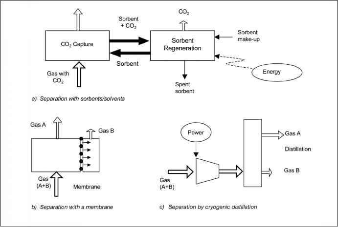
Figure 3.2 General schemes of the mainseparation processesrelevant for CO2 capture. The gas removed in the separation may be CO2, H2 or O2. In Figures 3.2b and 3.2c one of the separated gas streams (A and B) is a concentrated stream of CO2, H2 or O2 and the other is a gas stream with all the remaining gases in the original gas (A+B).
Figure 3.2 General schemes of the main separation processes relevant for CO2 capture. The gas removed in the separation may be CO2, H2 or O2. In Figures 3.2b and 3.2c one of the separated gas streams (A and B) is a concentrated stream of CO2, H2 or O2 and the other is a gas stream with all the remaining gases in the original gas (A+B).
preferentially separate H2 from a fuel gas stream, CO2 from a range of process streams or O2 from air with the separated O2 subsequently aiding the production of a highly concentrated CO2 stream. Although membrane separation finds many current commercial applications in industry (some of a large scale, like CO2 separation from natural gas) they have not yet been applied for the large scale and demanding conditions in terms of reliability and low-cost required for CO2 capture systems. A large worldwide R&D effort is in progress aimed at the manufacture of more suitable membrane materials for CO2 capture in large-scale applications.
3.1.3.3 Distillation of a liquefied gas stream and refrigerated separation A gas can be made liquid by a series of compression, cooling and expansion steps. Once in liquid form, the components of the gas can be separated in a distillation column. In the case of air, this operation is currently carried out commercially on a large scale. Oxygen can be separated from air following the scheme of Figure 3.2c and be used in a range of CO2 capture systems (oxy-fuel combustion and pre-combustion capture). As in the previous paragraphs, the key issue for these systems is the large flow of oxygen required. Refrigerated separation can also be used to separate CO2 from other gases. It can be used to separate impurities from relatively high purity CO2 streams, for example, from oxy-fuel combustion and for CO2 removal from natural gas or synthesis gas that has undergone a shift conversion of CO to CO .
3.1.4 Application of CO2 capture
The CO2 capture systems shown in Figure 3.1 can be cross-referenced with the differentseparation technologiesof Figure 3.2, resulting in a capture toolbox. Table 3.1 gives an overview of both current and emerging technologies in this toolbox. In the next sections of this chapter a more detailed description of all these technological options will be given, with more emphasis on the most developed technologies for which the CO2 capture cost can be estimated most reliably. These leading commercial options are shown in bold in Table 3.1. An overview of the diverse range of emerging options being investigated worldwide for CO2 capture applications will also be provided. All of these options are aimed at more efficient and lower cost CO2-capture systems (compared with the leading options). It is important o
Continue reading here:Postcombustion capture systems 331 Introduction
Was this article helpful?
Recommended Programs

Readers' Questions
-
Klaudia10 days ago
- Reply